Eskilstuna is the chief town in Eskilstuna municipality (90.00 inhabitants) and is situated about 110 km west of Stockholm.
The biggest sewage treatment plant in Eskilstuna is Ekeby STP which treats the sewage water from the chief town and the neighboring towns (about 95% of all sewage water in the municipality is treated at Ekeby; the rest is treated in 6 smaller local sewage treatment plants).
Eskilstuna sewage treatment plant has been built step by step. It started in 1956, when the first stage - mechanical treatment was put into operation (cleaning bars, pre-airation, sand catcher and primary sedimentation). In 1965, the second stage was put into operation - biological treatment (active sludge plant with airation basins and secondary sedimentation).
Eventually the third stage was put into operation in 1974, when a chemical precipitation plant was built.
At the beginning of the 1990s a new license application was sent to the county board, since the sewage treatment plant had earlier received only a temporary permission. In the application, it was suggested that the treatment demands should be fixed to:
BOD7 < 10 mg/l
tot -P < 0,3 mg/l.
When the application was submitted, a discussion had started in Sweden, about the need of nitrogen treatment.
As early as 1989 at the Ekeby plant the full-scale experiment concerning denitrification had been carried out by means of an external coal source (starch molasses). The experiment showed that it's possible to reduce nitrogen content, but in order to reach a low content of leaving phosphorus at the same time , it would be necessary to build a final filtration plant at the sewage treatment plant.
The costs necessary were appreciated to be at least 50 MSEK. Then, even the operation costs would be very high as an external coal source had to be bought for denitrification.
Because of the high costs, no nitrogen reduction was proposed in the license application.
In 1996, eventually the final cleaning demands were set, valid for the Ekeby sewage treatment plant - BOD7 <10mg/l, tot P <0.3 mg/l and the total nitrogen content mas 15 mg as an yearly average. During the time, the license application was discussed by the authorities, careful studies of the existing process at the Ekeby treatment plant were carried out, accounted for the flow and mass balance.
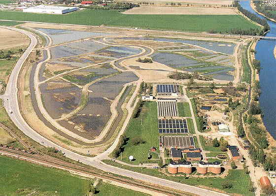
In Oxelösund and Hässleholm large wetlands were built . The research showed that it should be possible to receive enough high nitrogen reduction in a newly built wetland (about 2.5 t N/ha.year) for nitrified water.
Gradually, the work was aimed at a wetland solution to reduce the nitrogen content at the Ekeby sewage treatment plant.
There were favourable conditions , a.o. that all nitrogen in the sewage water would be nitrified in the existing active sludge plant (not in the winter months), there was suitable land etc.
A proposition for a construction of a wetland was prepared and shown to the board of Eskilstuna Energi & Miljö in August 1996.
The board decided in favour of a wetland. In the autumn of 1996 the plant was designed and inquiries were made to obtain a contract. The purchase of a contract took place in May 1997 and the construction work started in the middle of June 1997. Land work was finished in October 1997 and in the winter 1997/1998 the foundation laying and concrete laying were carried out.
In the spring and summer of 1998 the water plants were planted in the ponds and in April 1999 water from the sewage treatment plant was let into the ponds.